
Ender 3 v2 Pen Plotter
April 25, 2022 • nickw
 Last year I purchased myself an Ender 3 V2 3D Printer. It was a logical purchase, to compliment my home automation hobby, allowing me to design and print custom enclosures for miscellaneous ESPHome and Zigbee nodes.
It turns out having a CoreXY 3D printer allows you to do more than just 3D printing if you’re willing to get creative. For example, adding on a laser engraver.
In my case, I was tasked with automating the process of drawing an embroidery pattern onto fabric using a heat/friction erasable pen for my partner, Kate.
Unsurprisingly, there are services available which can do this, albeit using machine washable dye rather than heat reactive dye in most cases. However, in almost every case these are cost prohibitive for hobby embroidery projects and also happen to incur a long turn around time from order to delivery.
So as with most projects I undertake, rather than re-designing from scratch, I opted to start searching for existing projects. Surely someone had done this before! I managed to find a handful of models (e.g. Ender 3 v2 Pen Plotter addon ), however most of these either required you to fully remove the hotend assembly or did not accomodate mounting a BL-Touch levelling probe.
Fortunately I managed to find this model which both accommodated both of my requirements. It supported mounting of the BL-Touch probe without needing to remove the hotend assembly. I printed it and mounted it to the printer… job done… right? Unfortunately not. Due to the way it mounted it now meant that the hot-end carriage could no longer hit the x-axis limit switch. Not good!
From here, the only logical solution was to design my own, which accommodated for my specific requirements. I’ve been getting more and more familiar with Fusion 360 since buying the printer, so was confident to get straight to prototyping a design.
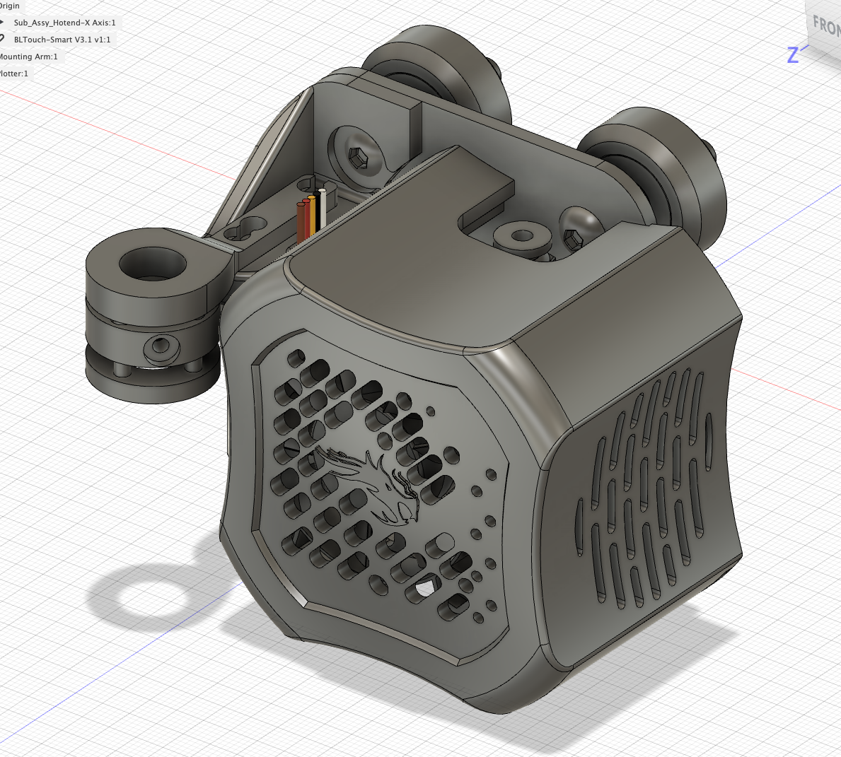
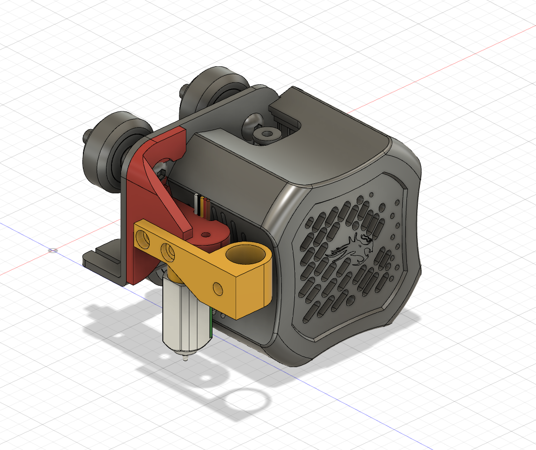
I started off by importing dimensionally accurate models of both the Ender 3 v2 print head assembly/x-carriage and the BL-Touch:
By doing so, I would be able to project the precise positions of mounting holes onto the sketches for component of my attachment, rather than measuring by hand with some amount of inaccuracies.
Another requirement I came to realise was that it would be useful would be the ability to remove the plotter attachment when it is not in use. As such I arrived at my first design iteration:
The design was relatively simple. Two main parts; a mounting arm to hold the BL-Touch probe to the hotend assembly, and a three-piece arm to hold the pen, which is mounted to the mounting arm using the same screws from the BL-Touch probe. The three-piece arm was designed to allow a pen to be mounted with some spring tension, however in actual fact once it was printed there was too much friction to provide any reasonable amount of travel. Back to the drawing board.
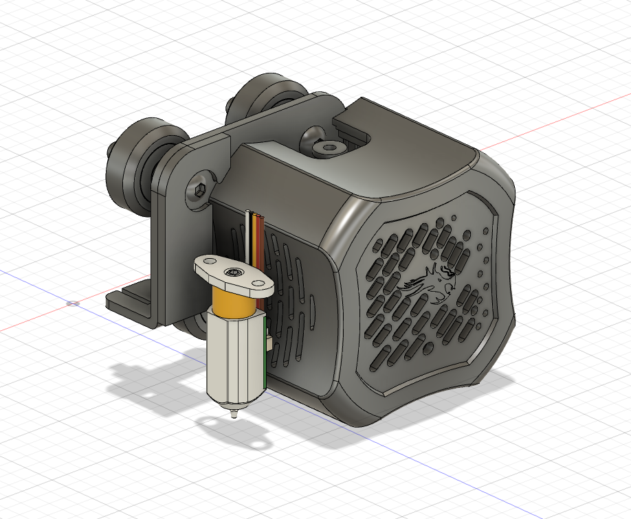
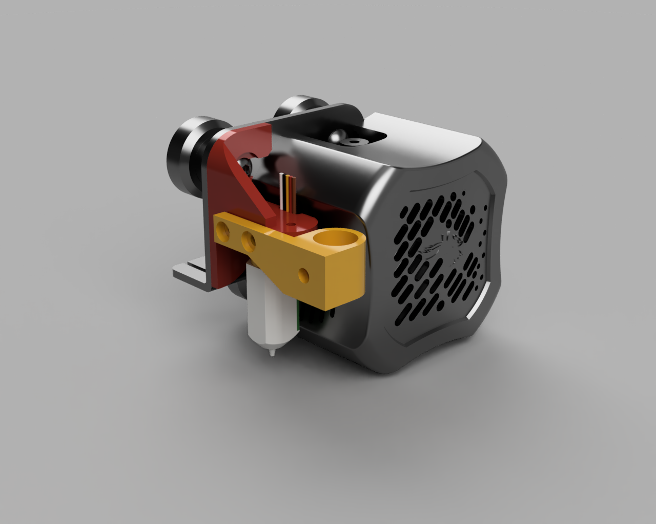
On to the next iteration, I re-thought the design. I reused the same mounting arm to the hotend assembly, but changed the mounting angle of the pen attachment. Instead, it would side-mount to the mounting arm using M3 bolts into heat-set inserts. I thought I would give this a try, without any tension mechanism, as an automatically leveled bed should suffice.
One printed, I came to realise that the side mounting again caused some interference with the x-axis limit switch, so I found that in order to solve this problem I needed to move the rear bolt closer to the front, and additionally provide a countersunk for the bolt head to sit inside.
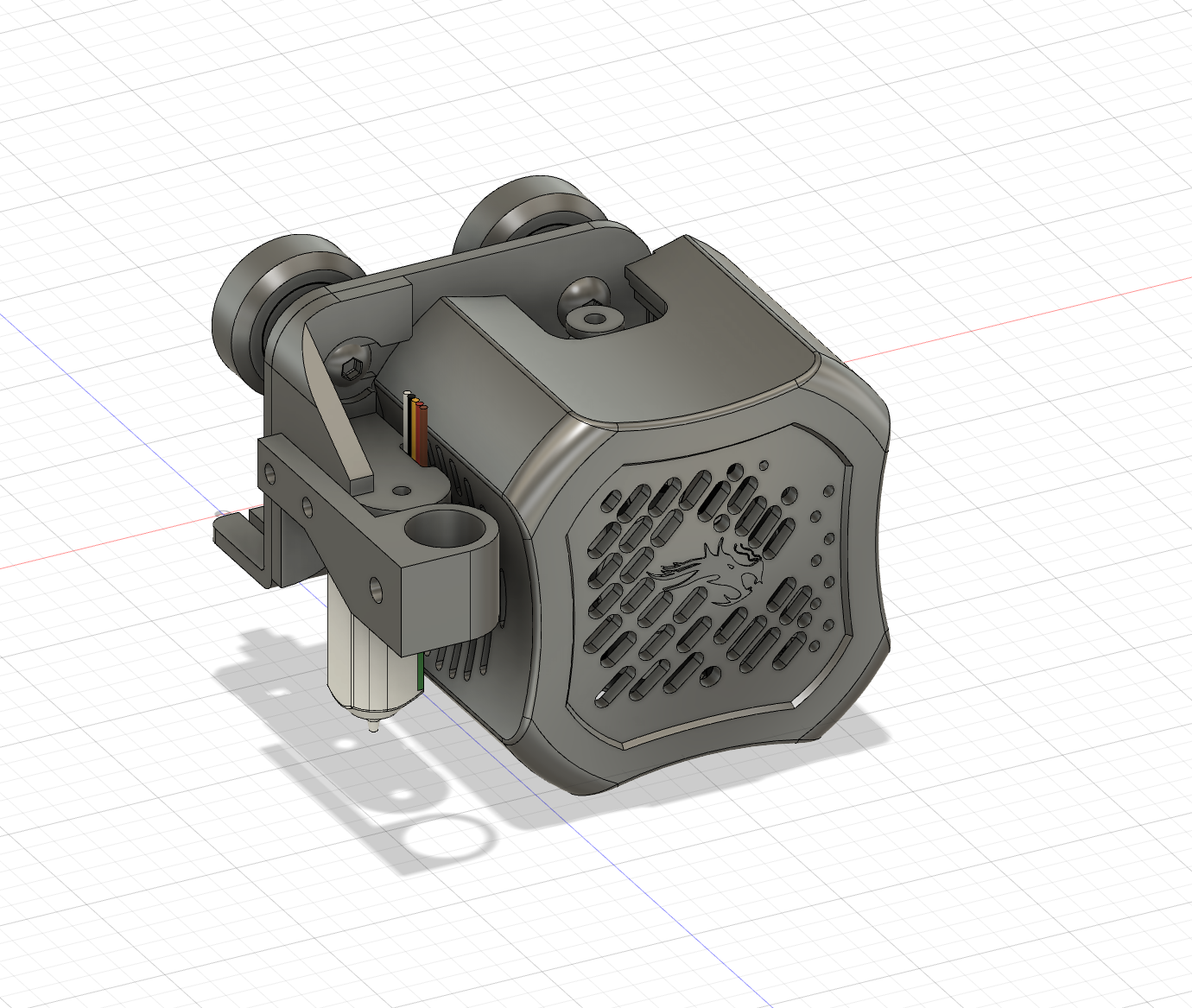
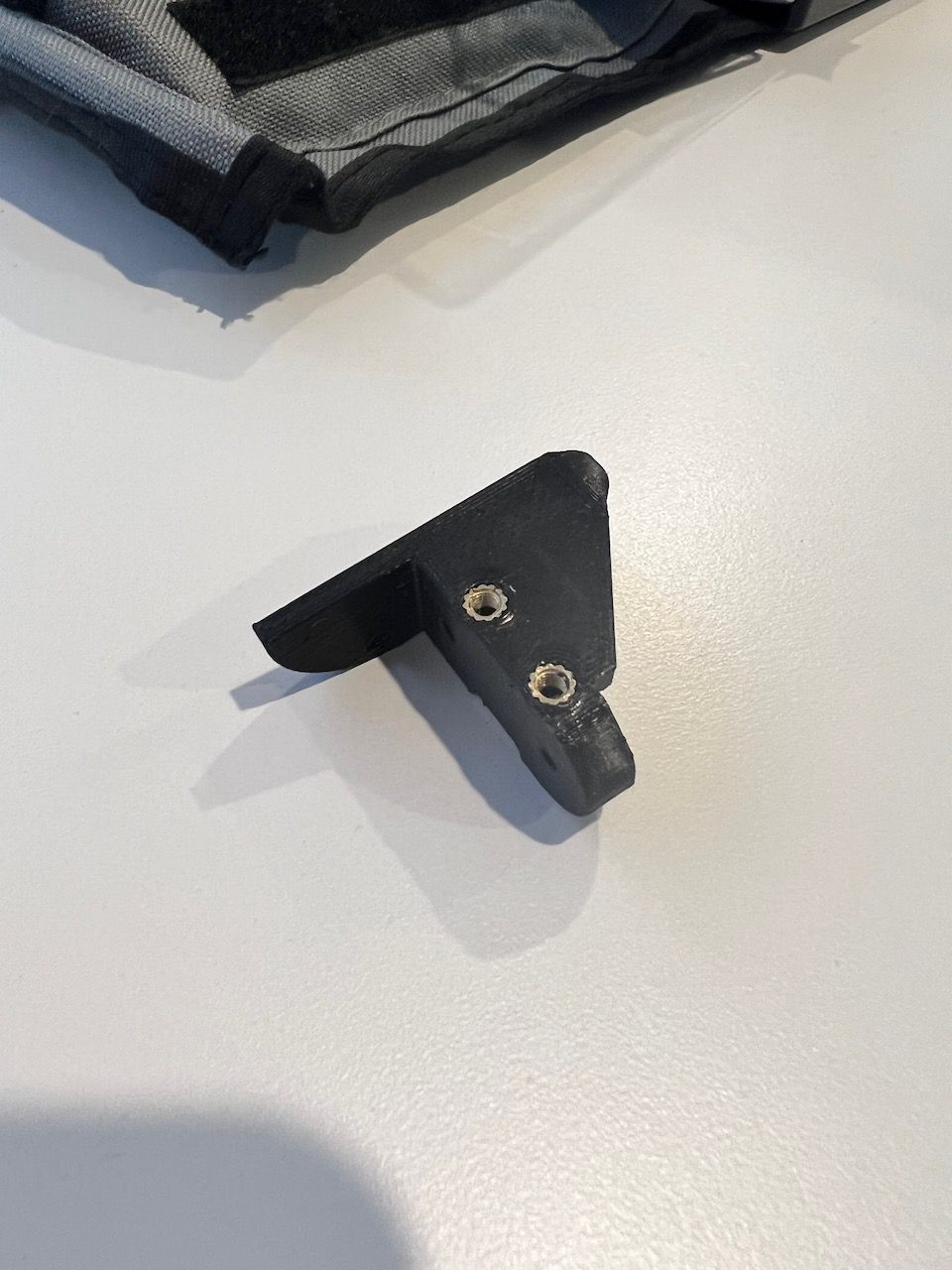
After a handful more prints and some more tweaks to the height of mounting arm and hole sizes, I had a final design:
Now, with the mounting bracket complete, it was time to move onto the software aspect of the project. Fortunately for me, this is a solved problem. Uri Shaked has written an excellent post about using Inkscape with the Gcodetools extension to produce plotting toolpats from SVG files. Inkscape isn’t the nicest software to run on MacOS, so the experience is a little clunky (and crashy), but it does the job. However, I plan on exploring other tools, like Inkcut, JScut, juicy-gcode, SVG-toGcode and hp2xx in due time.
Gcodetools allows you to specify a custom header and footer for produced gcode files. I used this to provide a more ergonomic printing experience by ensuring the printer was homed, bed levelling mesh is enabled, and the print timer is initiated to allow for on-the-fly tweaking of the z-height.
Header:
M420 S1 ; Enable Jyers Mesh
M75 ; Start print timer
G28 ; home all axis
Footer:
G1 Z20.00 F600 ; Move print head up
G1 X5 Y180 F9000 ; present print
M84 X Y E ; disable motors
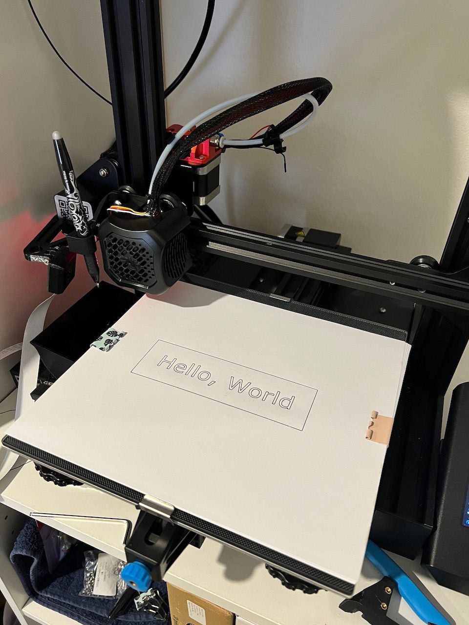
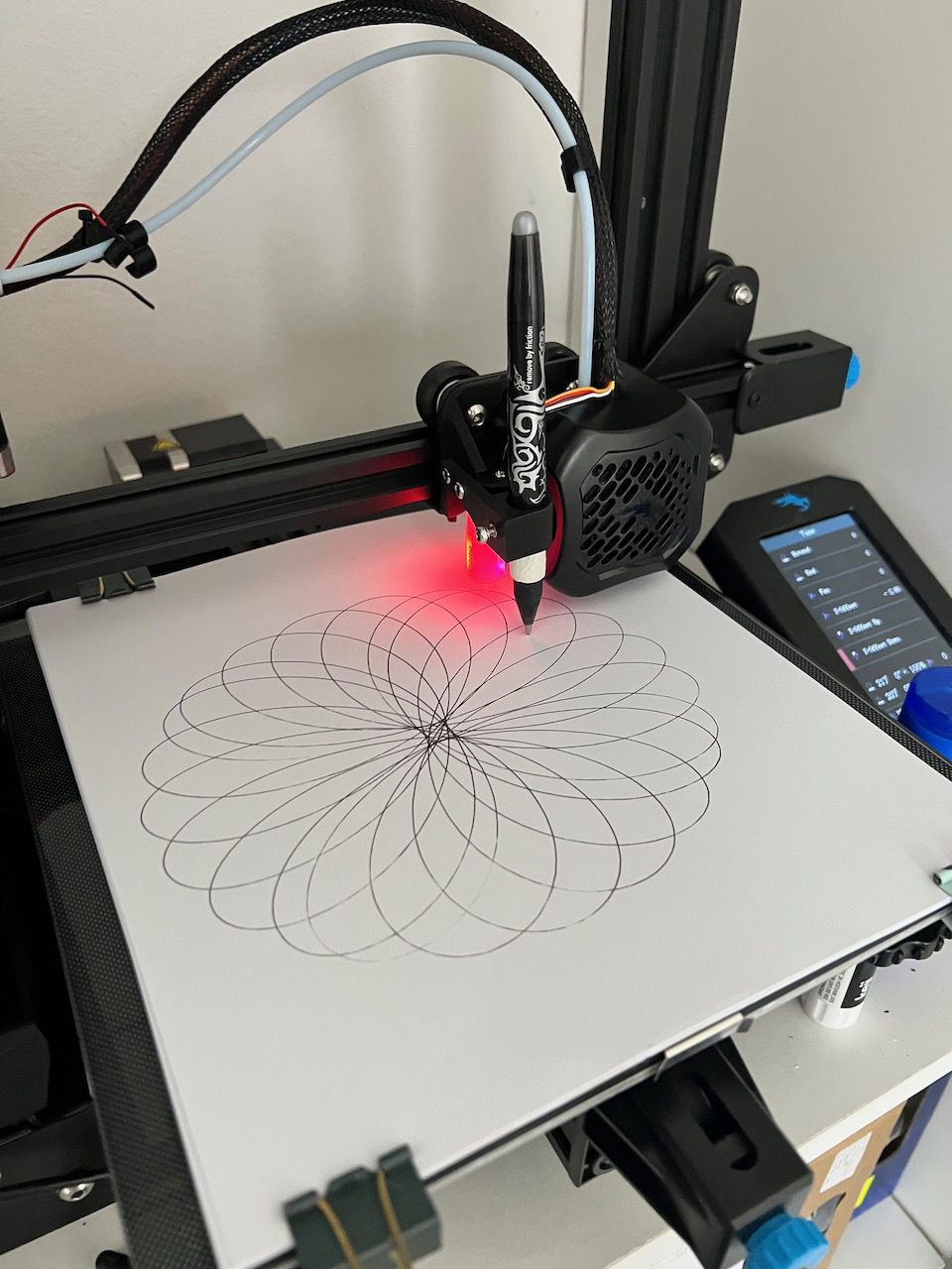
M77 ; Stop print timerNow, with some G-code produced, it was time for a test. As a software engineer, there’s no better way to test the output capability of something than to print("hello world"), and so that is exactly what I did:
Great success! From here, I did some further tests on fabric and found it worked just fine, albeit a little faint since more pen pressure resulted in snagging the fabric, so for fabric prints 2 or 3 passes is generally necessary. Beyond just plotting SVGs I’ve started to explore generative art using mathematical functions (like a spirograph). Here are a few pictures from testing and a video:


You can find the model for my Ender 3 V2 BL Touch Mount and Pen Plotter on Thingiverse and Thangs