
Quadcopter Arrived! (Most of it)
June 16, 2014 • nickw
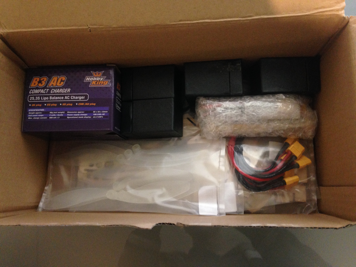
Today a majority of the electronic components of my quadcopter arrived. I received an email from the online shop saying that my order had been dispatched today and they included a tracking number. Upon checking the tracking, it turned out it had actually been posted on the 13th and it was “Delivered”. Being curious, I went downstairs, and there it was, a package on my door step. Excellent.
So it was a given I was going to have the rest of the afternoon off study – now that I had a new fun thing to play with.
As I am not building this from a kit, I had ordered all my parts individually and hoping for the best. For someone with such little hobby RC knowledge, google has definitely been my friend.
My package contained:
- 4x 10A ESC Combo Kits with a 1700Kv motor (not Kilovolts, RPM in K per volt)
- 1x Lipoly Balance Charger (For charging my Lipoly battery)
- 1x 2100mAh Lipoly Battery (2S, 30C)
- 1x Wooden Frame (Only cost $5, thought it would be worthwhile)
- 3x Different packs of Propellors
- 1x Power Distribution (Which I stupidly bought the one with the wrong plug)
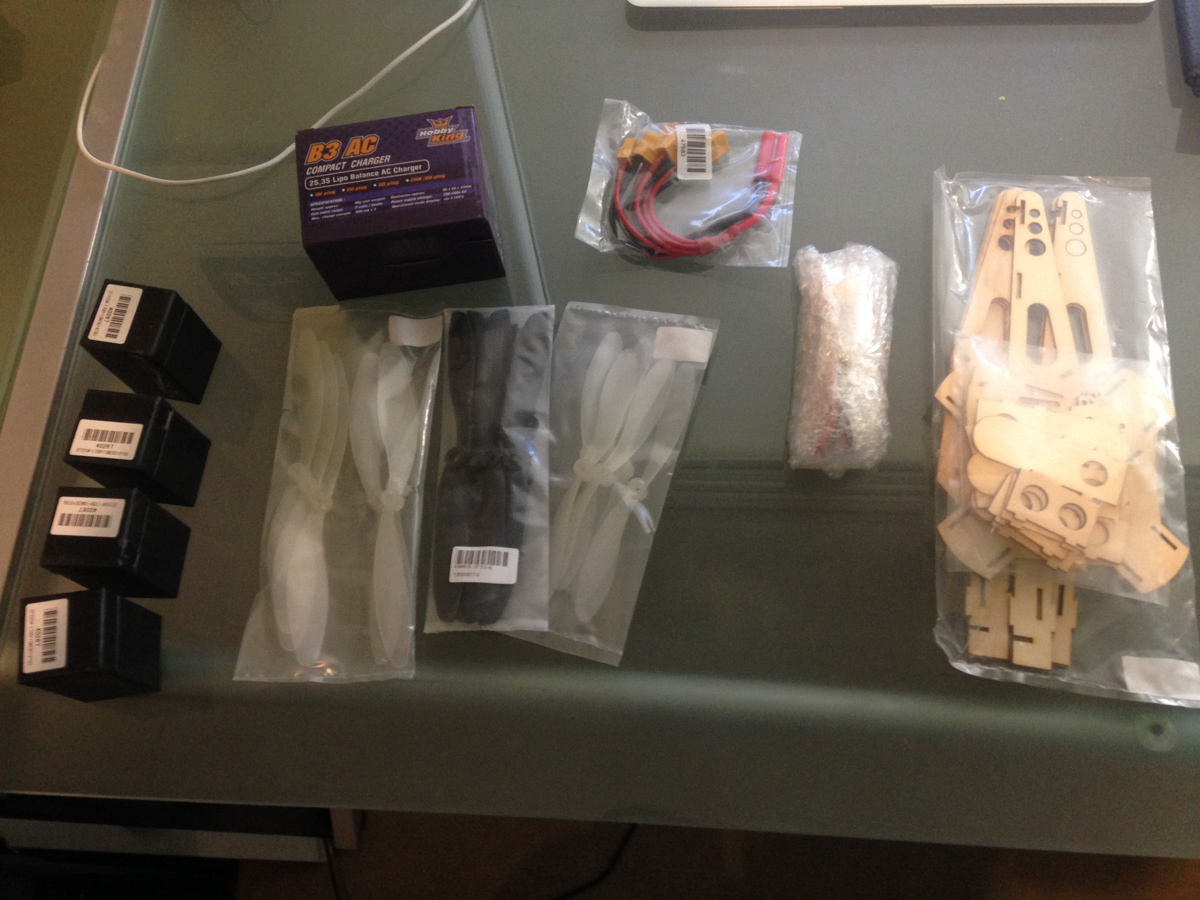
The contents of my package, laid out
So, Let’s get started. What on earth do all those numbers mean? I didn’t know – until I started looking them up. So, let me explain the motors to begin with.
Components
Motors
In quadcopters, you really do need to use brushless motors. This allows you to get maximum efficiency. Unfortunately, to run these, you need a ESC (Electronic Speed Controller). This turns a PWM signal into a voltage which is used to drive the motors. Conveniently, I found a kit which included an ESC and a motor of which were of a decent specification. I will cover connecting the ESC to a Raspberry Pi in a later section
Battery & Power
In newer RC, everyone is making the switch to Lipoly (Lithium Polymer) batteries. These are similar to those which are found in your phone – Lithium Ion. Unfortunately, they require a great deal of care when handling. We have seen many mobile phone explosions over the years due to Lithium Ion batteries exploding – This risk is just as, and even more evident in RC using Lithium Polymer batteries. This is due to the risky nature of the batteries. Very high capacity, in a high risk environment. Any puncture or shock to a battery can cause it to explode. See here
The charging process of a Lipoly battery is the same as Li-ion batteries. You will require a special charger. Most modern chargers and batteries have balance plugs, which makes charging safer and simpler. Older technology required you to balance the cells before charging and after charging. Failure to do so could lead to explosion.
Raspberry Pi
I already had a Raspberry Pi, which is great, and I plan to use it to drive the ESC’s, however it needs a source of power. I am contemplating connecting it to the ESC +5v output, however still deciding whether or not this is a good idea.
Propellors
There is so much choice when it comes to propellor choice. I chose 3 different kits each with 3x CCW and 3x CW props. This is required as the opposite rotation of the quad needs to be offset otherwise you will get unwanted yaw. The kits were to the following specs: 1x 7×4.5, 1x 7×6, 1x 6×5.
Other Things To Come
I’m still waiting on the brains of the quad. I still need to receive my I2c Altitude/Barometer/Temperature sensor as well as my I2C Gyro/Magnetometer/Accelerometer. Once they arrive, I will be ready to start writing the software. In the mean time, it’s a matter of assembling the hardware and doing all the connections.
Software
I lied, I actually did start writing some software today. It was only a basic python program to interface with the ESC’s via PWM on the GPIO pins on my Raspberry Pi.
It was a time consuming process learning how to communicate with the ESC’s via PWM. It’s practically undocumented as I suppose this is just a known thing in the Hobby RC world.
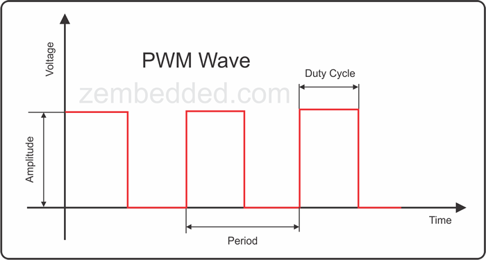
Basically to send a speed control to the ESC you need to use Pulse Width Modulation. This is a signal of a square wave. It has two variable parameters; the period and the duty. The period is the frequency and the duty is how long a pulse is to stay high for.
I knew all about how this worked, but had no clue how on earth to communicate within the range the ESC understood. After some light googling, I found out the range around ESC’s PWM signal. A width of 700 – 2000 microseconds is within the working range of a generic ESC. However the next issue was how to communicate using python using a value of microseconds. I’m lazy, and using math to turn this into a frequency in Hz unfortunate. Instead it turns out Python/RPi.GPIO has a class in PWM for a servo. It lets you set the value of microseconds directly. Awesome. Here’s a snippet of my code:
from RPIO import PWM
import time

max_PWM = 2000
min_PWM = 700

MOTOR_1_PIN = 25

servo = PWM.Servo()
time.sleep(2)

servo.set_servo(MOTOR_1_PIN, max_PWM)
time.sleep(5)
servo.set_servo(MOTOR_1_PIN, min_PWM)

time.sleep(3)
print("Servo Set Up")

while True:
 try:
 print("Enter New PWM Value:")
 ins = int(raw_input())
 servo.set_servo(MOTOR_1_PIN, ins)

 except KeyboardInterrupt:
 break

servo.stop_servo(MOTOR_1_PIN)
PWM.cleanup()
Unfortunately, that didn’t work. After much head scratching I still hadn’t worked out how to calibrate the PWM signal to the ESC.
To do a calibration process, you must turn on the GPIO PWM to the maximum signal, then switch on the ESC, then turn the PWM signal to minimum. After this occurs, you are now ready to start sending it PWM signal.
I modified my program to be more basic and let me give it any value i wished without the broken calibration code
from RPIO import PWM
import time

MOTOR_1_PIN = 25

servo = PWM.Servo()

while True:
 try:
 print("Enter New PWM Value:")
 ins = int(raw_input())
 servo.set_servo(MOTOR_1_PIN, ins)

 except KeyboardInterrupt:
 break

servo.stop_servo(MOTOR_1_PIN)
PWM.cleanup()
To do all this magic with the software I did need to connect everything up, so here are a few images of the current set up
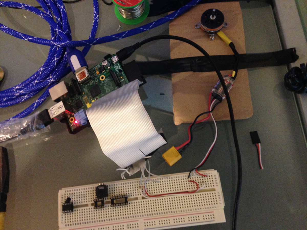
Breadboarding, connecting GPIO to the ESC via an old IDE cable.
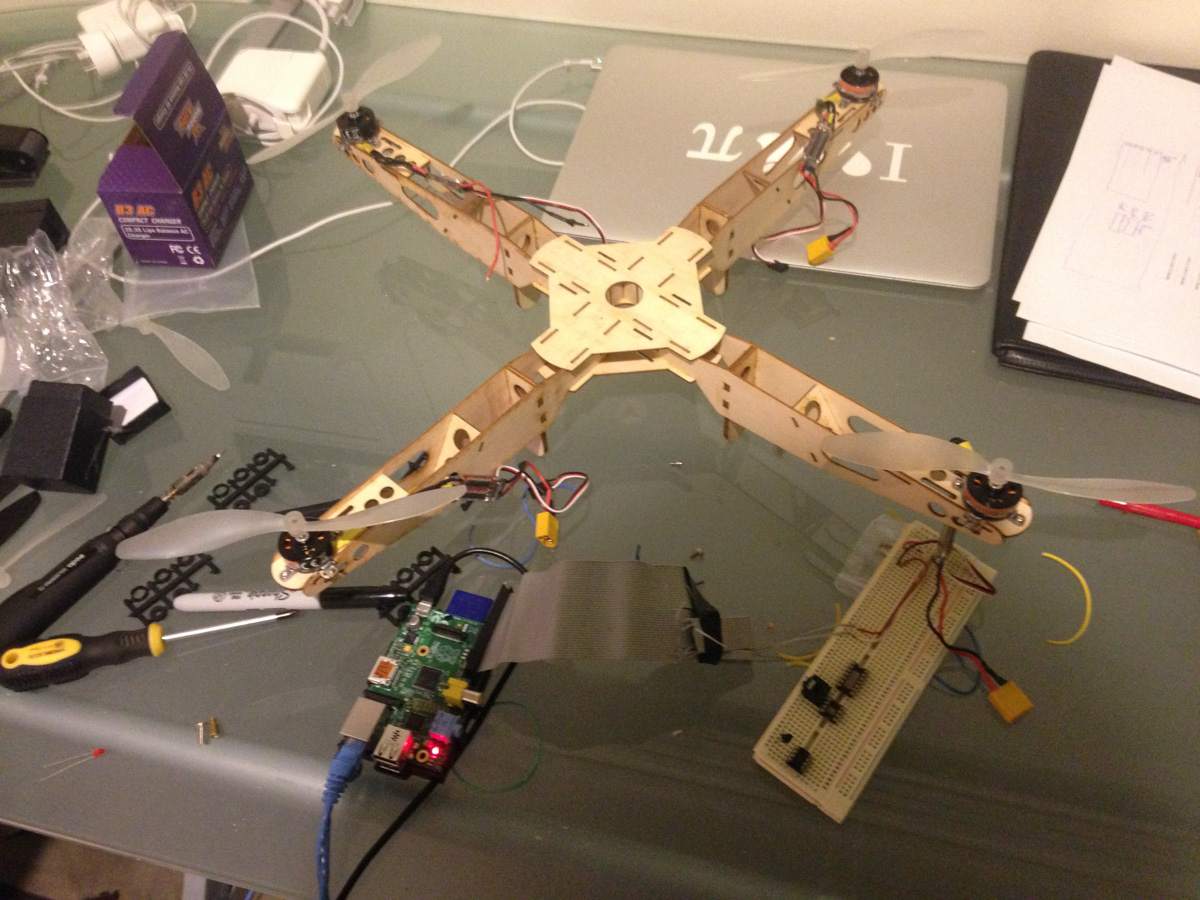
Cheap and nasty wooden frame – soon to be replaced
Anyway, that’s all for now, hopefully much more to come once everything is hooked up and ready to go!